Ambient Isp
IspAmb Equation
The standard CEA output includes two values of Isp:
Ivac = Isp at vacuum
Isp  = Isp at ambient pressure equal to nozzle exit pressure
Neglecting nozzle flow separation, the equation for calculating Isp at any ambient pressure (Pamb) is:
IspAmb = Isp - Cstar * Pamb * eps / Pc / 32.174
This can be verified on the LOX/LH2 Performance example of the Standard Examples page:
Ae/At                     1.00000   40.000
CSTAR, FT/SEC              7560.0   7560.0
CF                         0.6572   1.8351
Ivac,LB-SEC/LB              289.8    451.7
Isp, LB-SEC/LB              154.4    431.2
where:
IspAmb = 431.2 = 451.7 - 7560 * 2.17838 * 40 / 1000 / 32.174
Estimate IspAmb
RocketCEA includes a method for calculating ambient Isp. The estimate_Ambient_Isp method is called as follows:
IspSL, mode = ispObj.estimate_Ambient_Isp(Pc=500, MR=2.2, eps=50.0, Pamb=14.7)
The example above is for sea level performance where Pamb=14.7 psia. The returned Isp value considers both ambient pressure correction and potential nozzle flow separation.
The returned mode parameter is a string describing the nozzle flow condition. The script below demonstrates.
from rocketcea.cea_obj import CEA_Obj

C = CEA_Obj(oxName="LOX", fuelName="H2",  useFastLookup=0)
Pc=500.
MR=6.0
for eps in [2., 5., 7., 10., 20., 50.]:

    IspVac = C.get_Isp( Pc=Pc, MR=MR, eps=eps)
    IspAmb, mode = C.estimate_Ambient_Isp(Pc=Pc, MR=MR, eps=eps, Pamb=14.7)

    print('Pc=%4i  eps=%3i  IspAmb/IspVac= %6.2f/%6.2f  Mode= %s'%(int(Pc),int(eps), IspAmb, IspVac, mode))
The output from the script:
Pc= 500  eps=  2  IspAmb/IspVac= 329.49/343.22  Mode= UnderExpanded Pe=65.7213
Pc= 500  eps=  5  IspAmb/IspVac= 354.82/389.09  Mode= UnderExpanded Pe=18.3402
Pc= 500  eps=  7  IspAmb/IspVac= 354.32/402.22  Mode= OverExpanded Pe=11.8242
Pc= 500  eps= 10  IspAmb/IspVac= 346.25/414.56  Mode= OverExpanded Pe=7.49482
Pc= 500  eps= 20  IspAmb/IspVac= 316.16/434.70  Mode= Separated Psep=4.84056, epsSep=14.2
Pc= 500  eps= 50  IspAmb/IspVac= 309.31/455.27  Mode= Separated Psep=4.84056, epsSep=14.2
Thrust Coefficient
The thrust coefficient (Cf) is normally defined based on the ambient delivered thrust as:
Cf = Famb / (Pc * At)

where: Famb=ambient thrust, Pc=chamber pressure, At=throat area
CF is the name given to the thrust coefficient in the CEA output. (shown above in the Ambient Isp section)
When calculating CF, CEA assumes that the ambient pressure is equal to the nozzle exit pressure.
(displayed as P, ATM or P, BAR in the CEA output)
This may not be the Cf of interest since it is much more common to want the Cf in vacuum or at sea level.
RocketCEA (as of version 1.1.4) provides two methods to obtain a thrust coefficient at any given ambient pressure;
get_PambCf and getFrozen_PambCf.
These routines return three parameters:
CF - the value printed out by CEA
CFamb - the value calculated by RocketCEA for the given ambient pressure
mode - a description of the nozzle operating conditions at ambient pressure
The following script calls get_PambCf for the four nozzle operating domains of interest,
under-expanded, Pexit equals Pambient, over-expanded and separated flow.
from rocketcea.cea_obj import CEA_Obj

Pc=1000.0
MR=6.0
Pamb=14.7

ispObj = CEA_Obj( oxName='LOX', fuelName='LH2')

# get nozzle area ratio that has Pexit equal to Pamb
eps_pamb = ispObj.get_eps_at_PcOvPe(Pc=Pc, MR=MR, PcOvPe=Pc/Pamb)

# run under-expanded, Pexit equals Pambient, over-expanded and separated flow
for eps in [4., eps_pamb, 12., 40.]:
    CFcea, CFamb, mode = ispObj.get_PambCf( Pamb=Pamb, Pc=Pc, MR=MR, eps=eps)
    print('eps=%7g, CFcea=%7g, CFamb=%7g, mode=%s'%(eps, CFcea, CFamb, mode) )
The output of which is:
eps=      4, CFcea= 1.4319, CFamb=1.56337, mode=UnderExpanded (Pe=47.5806)
eps=9.47259, CFcea=1.62334, CFamb=1.62333, mode=Pexit = 14.7034
eps=     12, CFcea=1.66568, CFamb=1.61783, mode=OverExpanded (Pe=10.7148)
eps=     40, CFcea=1.78854, CFamb=1.45502, mode=Separated (Psep=4.21395, epsSep=27.3156)
Nozzle Flow Separation
The IspAmb equation above neglects the fact that, as ambient pressure rises, eventually the nozzle flow separates. Flow separation can be quite violent and, in fact, can be the major structural design criteria of engines designed for it.
The Parasol Example page devotes a more detailed exploration of ambient performance and flow separation.
The following RocketCEA script runs nozzle separation calculations and launches Microsoft Excel in order to plot the results. (works on Windows only, see: ODSCharts for a Linux solution.)
from rocketcea import separated_Cf
from rocketcea import xlChart
from rocketcea.cea_obj import CEA_Obj

pc=108.0
eps=5.0
oxName= 'N2O4'
fuelName='MMH'
mr = 1.65
Nsteps = 20

ispObj = CEA_Obj(oxName=oxName, fuelName=fuelName)

IspODE, Cstar, Tcomb, mw, gam = ispObj.get_IvacCstrTc_ChmMwGam( Pc=pc, MR=mr, eps=eps)

pcArr = [100.0, 150.0, 200.0]

rs = [ [ 'Pamb','Cf/Cfvac', 'Pc','mode'] ]
for pc in pcArr:
    for i in range( Nsteps+1):
        Pamb = 14.7 * i / Nsteps
        Cf, CfOverCfvac, mode = separated_Cf.ambientCf(gam=gam, epsTot=eps, Pc=pc, Pamb=Pamb)

        rs.append( [ Pamb, CfOverCfvac, pc, mode] )
    rs.append(['','','',''])

xl = xlChart.xlChart()
xl.xlApp.DisplayAlerts = 0  # Allow Quick Close without Save Message

myTitle = "%s/%s Ambient Performance at Area Ratio=%.1f\n"%(oxName, fuelName, eps) +\
    "Pc Range = %g - %g psia"%(min(pcArr), max(pcArr))
xl.makeChart(rs,
            title=myTitle,nCurves = 1,
            chartName="Performance",
            sheetName="FillData",yLabel="Cfamb/Cfvac", xLabel="Ambient Pressure (psia)")
xl.setYrange( 0.6, 1.0)
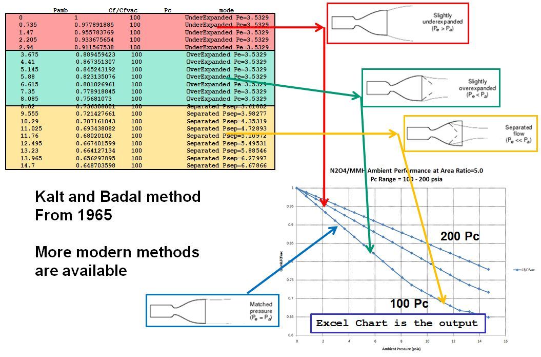
The script creates an Excel spreadsheet of ambient performance calculations shown in the image below. A table of nozzle conditions is shown in the upper left corner of the image. A graph of ambient pressure vs nozzle Cf ambient divided by Cf vacuum is shown in the bottom right corner of the image:
Note
There are more modern methods of estimating flow separation than Kalt and Badal from 1965.
Any detailed engine design that needs to consider flow separation would need to employ improved methods.